









- bhavya gada
- No Comments
If you miss the checks before backfill, you can end up with failed inspections, settlement, drainage problems, and costly rework. I’d boil this guide down to one point: verify the plan, verify the site, verify the install, and document everything before the system is buried.
In plain terms, this checklist covers the full job from start to finish, similar to our other professional landscape services:
- Start with stamped plans and confirm sizing, storage volume, discharge rate, and drain-down time.
- Get permits and utility locates before digging. In Maryland, permit review often starts when a project adds 5,000 to 10,000 square feet of impervious area.
- Check the site conditions against the drawings, including grades, invert elevations, soils, and groundwater.
- Excavate and prepare the base the right way, including subgrade proof-rolling and 95% Standard Proctor compaction where required.
- Install chambers, pipes, wraps, and outlet controls to plan, with photo records before backfill.
- Backfill in 6- to 12-inch lifts, keep heavy equipment off the system until minimum cover is in place, and restore grade so runoff still moves as planned.
- Close out with testing and records, including as-builts, density reports, and drain-down checks. Many systems are expected to drain within 72 hours after a 24-hour storm event.
The short version: I’d treat this as a pass-or-fail process, not a rough field guide. Small mistakes in buried work can turn into big repair bills later.
The article below walks through each stage in order so you can check the job before, during, and after installation.
Underground Detention System Installation Checklist: Step-by-Step Guide
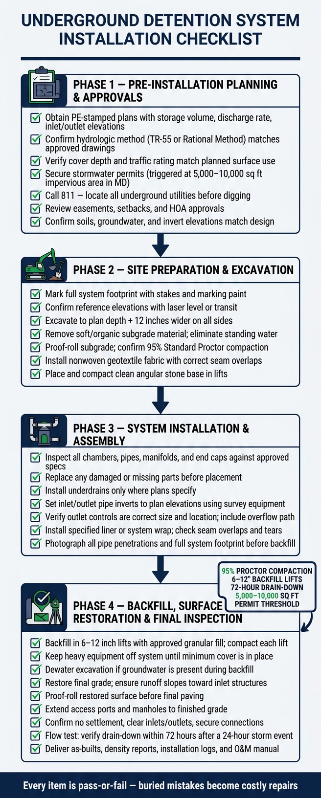
1. Pre-Installation Planning and Approvals Checklist
Confirm Engineering, System Sizing, and Stormwater Design
Start with PE-stamped plans for every underground detention system. That keeps the field crew working from the same approved design instead of making calls on the fly.
Those plans need to show the full stormwater picture: storage volume, discharge rate, inlet and outlet elevations, plus the required dimensions, depth, and slope. Before excavation starts, verify that the hydrologic method used – usually TR-55 or the Rational Method – is clearly documented and that the pre- and post-development runoff calculations match the approved drawings [1][4].
The system also has to do two things the design calls for: store runoff and drain within the approved drawdown time. If the plans specify a lined system, make sure the wrap and liner specs match the approved design exactly [1].
Also confirm that the cover depth and traffic rating fit the planned surface use. A system under a landscaped area is one thing. A system under a drive lane or parking area is another [1][3].
Secure Maryland Permits and Locate Underground Utilities
Once the design is set, check approvals and utility clearances before any dirt moves. In Maryland, stormwater permits are often triggered when a project adds 5,000 to 10,000 square feet of impervious surface [4]. MS4 projects usually need annual inspections and documentation [2]. It pays to talk with the local permitting office early, not after the schedule gets tight.
Call 811 before excavation. Locate water, sewer, gas, electric, and telecom lines so the crew doesn’t run into avoidable conflicts [1]. Review recorded easements too, and confirm required setbacks from property lines and foundations [3]. If the site is in an HOA community, get written approval before permit submittal.
Check Site Conditions and Drainage Connections
Before excavation begins, compare the engineered drawings with actual field conditions. That’s one of the simplest ways to avoid failed inspections and expensive rework.
Verify grades, drainage patterns, and outfall limits using current survey data. Confirm that inlet and outlet invert elevations line up with the design plans [1][4].
Then review the geotechnical report to confirm soils, permeability, and seasonal high groundwater [1][5]. If the soils data does not support infiltration, the design should move to a lined detention system with an outlet control structure [1]. If groundwater sits above the system invert, include anti-flotation measures such as anchor pads or hold-down straps [4].
Once the plans, permits, and site data all line up, the project is ready for layout and excavation.
sbb-itb-843f8be
2. Site Preparation and Excavation Checklist
Mark the Footprint and Verify Elevations
With approvals wrapped up, it’s time to lay out the site and start excavation. Mark the entire system footprint on the ground with stakes and marking paint. Check that those dimensions match the approved engineering plans exactly. Then use a laser level or transit to confirm reference elevations at the corners and along the layout. If anything is off, fix it before digging begins.
Also check setbacks from foundations, property lines, utilities, and hardscape installations. These clearances often look fine on paper but get missed in the field. A layout mistake takes minutes to fix now. Mid-excavation, that same mistake can cost hours.
Excavate to the Required Depth and Prepare a Stable Subgrade
Excavate to the depth listed on the plans, and extend the excavation at least 12 inches wider than the system footprint on all sides. That extra space gives crews room for pipe connections and backfill compaction [4].
At design depth, the subgrade needs to be firm, uniform, and free of soft or organic material. Remove and replace any loose or spongy sections with stable fill. Clear out standing water before compaction [4].
Proof-roll the subgrade with a loaded vehicle to expose weak areas. Then confirm at least 95% Standard Proctor compaction with a nuclear density gauge [4]. Take photos of the compacted subgrade before it gets covered.
Place Geotextile and Foundation Stone Correctly
After the subgrade passes inspection, install nonwoven geotextile fabric across the bottom and up the sides of the excavation. Make sure seam overlaps match the manufacturer’s specs. Check the fabric for tears before adding stone.
Next, spread clean, angular stone over the geotextile to the thickness shown on the plans. Place the stone in lifts, and compact each lift so the finished base is level and stable.
Once the base passes inspection, the system is ready for placement.
3. System Installation and Assembly Checklist
Inspect Materials Before Placement
Once the base passes inspection, move to system placement and connection. Start by checking every delivered part. It’s much easier to swap out a bad chamber or damaged pipe now than after the system is covered.
Match chambers, pipes, manifolds, and end caps to the approved specs. Look for shipping damage, and replace any missing or damaged parts before installation starts.
Set Chambers, Underdrains, and Connections to Plan
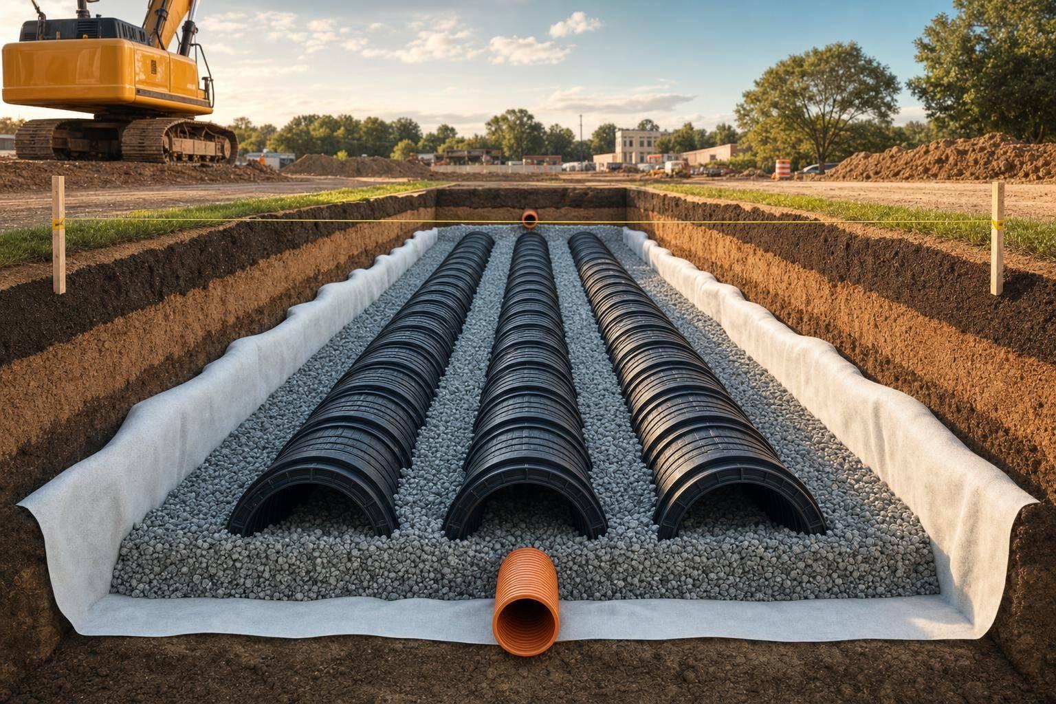
Install underdrains only where the plans show them, and place them on the compacted stone bedding. Then set the chambers according to the approved layout.
Set inlet and outlet pipe inverts to the plan elevations. Use survey equipment to confirm each connection point before the system is covered. Also verify that outlet controls are the right size and in the right location [2][4]. Include an overflow path for storms above the design event [2].
Wrap and Protect the System Before Backfill
Before backfill starts, install the specified liner or system wrap over the assembled chambers. Check that seam overlaps meet the manufacturer’s requirements, and inspect the fabric for tears.
Using the wrong wrap can cause rejection or system failure [1]. For example, don’t use permeable geotextile where a liner is required.
Photograph all pipe penetrations, sealed connections, and the full system footprint before backfill [1]. Once the system is covered, you can’t verify those details without reopening it.
4. Backfilling, Surface Restoration, and Final Inspection Checklist
Backfill in Lifts and Keep Heavy Loads Off the System
Once the chambers and wrap are checked, start backfilling in controlled lifts. Use approved granular fill in 6- to 12-inch lifts, and compact each lift to the approved density. Poor compaction is one of the main reasons systems settle or fail too soon [4].
Don’t dump a big load of fill all at once. That kind of uneven pressure can shift chambers, put stress on pipe joints, and leave voids behind [1][4]. Heavy equipment should stay off the system until the approved minimum cover is in place [1][4]. If groundwater is present, keep the excavation dewatered during backfill so voids don’t form [4].
Restore the Surface and Maintain Proper Drainage
After the cover is in place, finish the grade and make sure runoff still moves away from the system. Then restore the surface, whether it’s lawn, planting, patio, driveway, or walkway. The final grade should still slope toward the planned inlet structures, and water should not pond over the detention area.
Proof-roll the restored surface to catch settlement before final paving [1]. Extend access ports, manholes, and inspection hatches to finished grade so crews can still use them later for maintenance [4]. Surface use also needs to match the system’s rated load capacity [4].
Complete Inspection, Documentation, and Handoff
With the surface restored, it’s time for the last round of field checks. Final inspection should confirm:
- There’s no visible settlement or misalignment
- Inlets and outlets are clear of debris
- All accessible connections are secure [1][3]
Flow testing can also help confirm the system drains within the 72-hour maximum drain-down window typically required after a 24-hour storm event [3].
As-built records should include final elevations at each inlet, outlet, access point, and key corner of the system footprint. They should also include nuclear density test reports, installation logs, and material tickets for each lift [1]. A project-specific operations and maintenance manual should be turned over as well, with access-point locations and inspection intervals [1].
If final grading, drainage fixes, or yard repairs are still needed after installation, Pro Landscapes MD can help with those last steps across central Maryland.
StormTech Underground Detention System Installation
Conclusion: The Key Checks That Prevent Drainage Failures and Rework
Every step in the checklist has a direct effect on how the system works. Approved plans and permits set the design. Correct excavation and invert elevations help prevent settlement. Proper cover and backfill protect load capacity. Complete documentation makes future maintenance much easier.
These checks matter most after the trench is closed and the surface is put back. That’s when mistakes get buried too. And buried systems usually fail when those hidden steps get rushed.
Quality control during installation often makes the difference between a system that lasts and one that fails early. A checklist cuts out guesswork. Each item should have a clear pass-or-fail record, so there’s no gray area and no room for mixed calls at closeout.
This checklist helps protect your investment, control runoff, and avoid costly rework.
If you need final grading, drainage connections, or yard restoration in central Maryland, Pro Landscapes MD can help.
FAQs
Who should inspect the system before backfill?
Before backfilling starts, the underground detention system should be inspected by the right field inspection personnel. This usually means a third-party inspector, a licensed professional engineer, or other designated field representatives named during the mandatory pre-construction meeting.
This step helps confirm the system was installed according to the approved plans and specifications.
What happens if groundwater is found during excavation?
If groundwater shows up during excavation, notify the design engineer right away so they can assess site conditions. If that leads to any design changes, document them.
Water from other sources can often be handled by de-watering the excavation and removing sediment. Groundwater intrusion is different. It usually needs professional engineering oversight to protect the system’s structural integrity and performance.
How do I know if my site needs a lined detention system?
You may need a lined underground detention system when site or soil conditions call for a barrier. A liner is often used when you can’t keep at least 2 feet of separation between the system’s lowest point and the seasonal high-water table.
An impervious liner may also make sense in contaminated soils. Always confirm the project requirements with your approved plans and a professional engineer.
Chat with Us