









- bhavya gada
- No Comments
If I get six design calls right, a media filter drain is far less likely to clog, pond, or wash out. For Maryland homes, I’d focus first on the drainage area, then the runoff source, media depth, pretreatment, underdrain layout, and overflow and maintenance access.
Here’s the short version:
- I start by mapping every surface that drains to the system, including roofs, driveways, patios, and sloped lawn areas.
- I check the runoff source because roof water is often cleaner than driveway runoff, which can carry more sediment and oil.
- I use at least 18 inches of sand-based media and stick with clean, washed ASTM C-33 sand.
- I add pretreatment at the inlet, such as a grass strip, gravel entry zone, or sediment chamber, to keep fines and debris out of the bed.
- I lay out a perforated underdrain with clean-outs or observation ports so I can inspect and flush the system.
- I keep a separate overflow path for storms that exceed treatment capacity.
- I make sure crews can reach the inlet, pretreatment area, media surface, clean-outs, and outlet for service.
A few numbers matter here. The media bed should have a surface area that matches the runoff load, and the filter layer should be 18 inches minimum. Also, if the bottom of the drainage layer sits too close to the seasonal high water table, drainage can slow and the bed may stay wet between storms.
| Design point | What I check | Why it matters |
|---|---|---|
| Drainage area | All surfaces draining to the bed | Sets system size |
| Runoff source | Roof, driveway, or mixed flow | Affects sediment load and clogging risk |
| Media depth | 18 inches or more | Supports treatment and drainage |
| Media type | Washed ASTM C-33 sand | Helps steady flow through the bed |
| Pretreatment | Grass, gravel, or chamber | Cuts sediment at the inlet |
| Underdrain | Perforated pipe with clean-outs | Moves treated water out and allows service |
| Overflow | Separate bypass route | Limits washout and surface ponding |
| Access | Reach all service points | Makes inspection and cleaning more likely |
If I had to sum it up in one line: size it to the runoff, protect it from sediment, drain it well, and make it easy to maintain.
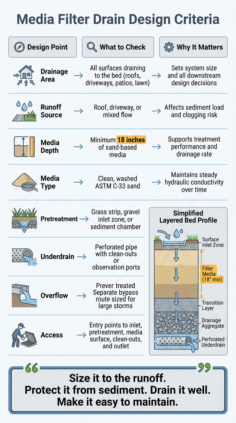
Media Filter Drain Design Criteria: 8-Point Checklist for Maryland Homes
Introducing the Advanced Drainage System BayFilter Design Tool Video
sbb-itb-843f8be
Sizing the Drainage Area and Identifying Runoff Sources
With the system location set, the next step is figuring out how much area the drain needs to treat.
Defining the Contributing Drainage Area
Start by identifying the full contributing drainage area. Then line up the system layout with the runoff source and the load you expect it to handle.
The contributing drainage area includes every surface that sends water toward the system. That can include rooftops, driveways, patios, and graded lawn areas. If water flows from that surface into the drain, it counts.
Getting this map right is the starting point for every other sizing choice. If the drainage area is off, the rest of the design can drift off course too.
How Runoff Source Affects Design
Not all runoff behaves the same way.
Roof runoff, driveway runoff, and mixed site runoff each put different demands on pretreatment and media selection. Roof runoff is often cleaner. Driveways and parking areas, on the other hand, tend to carry sediment, oils, and fine particles. Those materials can load the media bed faster and lead to clogging sooner.
That’s why it helps to identify the main runoff source early. Once you know where most of the water is coming from, you can make better calls on pretreatment and the media specification.
Media Area Ratios and Basic Water Quality Sizing
That same sizing work also affects media depth, layering, and underdrain layout.
At the center of it is the ratio of filter media surface area to contributing drainage area. This ratio helps show whether the system can handle runoff volume without bypassing flow or clogging too soon. If the media area is too small for the drainage area feeding it, the system can struggle under even normal stormwater loads.
For residential media filter drains in Maryland, keeping that ratio in line with the site’s impervious cover and runoff character is a core design check. It’s one of those details that can look minor on paper but has a big effect once water starts moving through the system.
Filter Media Depth, Layering, and Underdrain Layout
Once you’ve sized the drainage area and identified the runoff source, the next step is the bed profile. Depth, media type, and underdrain layout all shape how well the system treats runoff and how fast it drains after a storm.
Media Depth and Material Selection
For residential systems, use at least 18 inches of sand-based media. That depth gives you a good balance between treatment and drainage.
Depth alone isn’t enough, though. The media itself needs to be right. Use clean, washed ASTM C-33 sand. Sand that is uniform and properly graded is less likely to clog with fines, and it helps keep hydraulic conductivity steady over time.
Layered Profile from Surface to Outlet
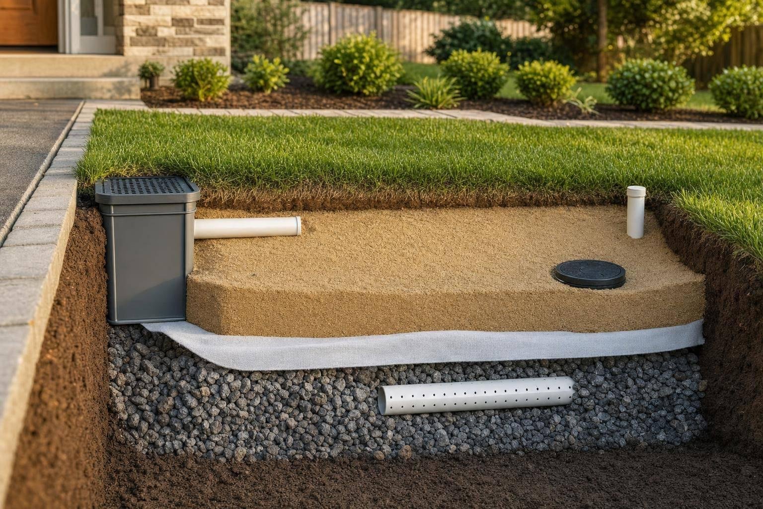
Build the system in layers from top to bottom: the surface inlet zone, filter media, an optional transition layer, drainage aggregate, and a perforated underdrain. Each layer has a clear job.
That setup helps filtered water move down through the bed and out to the outlet without shifting or disturbing the media above it.
Underdrains, Clean-Outs, and Groundwater Separation
Place a perforated underdrain at the base of the drainage aggregate. Add clean-outs or observation ports so the system can be checked and serviced without guesswork.
It also helps to keep the bottom of the drainage aggregate above the seasonal high water table. If it sits too low, the bed can stay saturated between storms and lose drainage capacity.
Pretreatment, Inlets, and Overflow Control
After the bed profile is set, the next job is protecting the inlet.
Pretreatment Methods That Protect the Media Bed
Pretreatment shields the media bed from sediment and debris. Good options include a grass filter strip, a gravel inlet zone, or a sediment chamber. This step matters most for runoff with a heavy sediment load.
Inlet Distribution and Erosion Control
Inlet design shapes how runoff enters the bed. Use a level spread entry so flow moves in evenly across the full inlet width. Pair that with a stone apron at the entry point to cut the force of incoming water and stop jetting that can erode the media surface.
Overflow and Bypass Design for Larger Storms
Once the inlet is under control, add a separate overflow path for storms that go beyond treatment capacity. Bigger storms can send more water through the system than the media bed is built to handle. If there’s no dedicated overflow or bypass route, that extra flow can wash out the media surface or lead to ponding above the bed. Size and place the overflow so it turns on before water backs up into the filter zone.
Maintenance Access and Final Design Priorities
Building in Access for Inspection and Maintenance
Once the system is built to move water the right way, it also needs to stay easy to service. That means planning access for inspection, cleaning, and repairs from the start.
Entry points should let crews remove sediment from the inlet zone and pretreatment area without disturbing the media bed. The inlet and outlet should both be easy to reach for visual checks after storms. And if flow slows down or stops, the underdrain should be accessible for flushing.
Maintenance Checkpoints That Should Influence Design
The design should also make routine inspection fast and predictable. After installation, service checks should cover five areas:
- the inlet for debris or blockage
- the pretreatment zone for sediment buildup
- the media surface for ponding that does not clear between storms
- the clean-outs for signs of clogging in the drainage layer
- the outlet for steady flow after rain
If any of these spots are hard to reach, maintenance tends to get skipped. When that happens, the system usually degrades faster.
Key Criteria for a Durable Maryland Media Filter Drain
These details work together to keep the system working through repeated storms. In practice, a Maryland media filter drain that resists clogging and stays serviceable comes down to six design-stage choices: contributing drainage area, runoff source, media depth, pretreatment, underdrain layout, overflow path, and built-in access for inspection.
FAQs
How do I calculate the drainage area?
Measure all impervious surfaces that drain to the system. That includes rooftops, driveways, sidewalks, and patios.
In Maryland, a common design standard is to size the bioretention area at 5% to 10% of that total. Put more simply, the system is often built to handle runoff from an area 4 to 20 times its own size. Another way to look at it: plan for 50 to 250 square feet of filter area for every 1,000 square feet of impervious surface.
When does a media filter drain need pretreatment?
Pretreatment helps manage sediment and debris before runoff reaches the main filtration media.
Features like grass channels, filter strips, pea gravel diaphragms, sumps, and forebays give larger particles a chance to settle out first. That first step matters. It helps prevent clogging, cuts maintenance, extends the life of the system, and keeps the filtration media working well for stormwater treatment.
How can I tell if the underdrain is failing?
Watch how the area drains after rain. If water sits there for more than 48 hours, that’s often a sign of a pipe blockage or compacted soil.
It also helps to inspect underdrain outlets at least twice a year, ideally in spring and fall. Look for sediment, debris, and root intrusion. If the system starts draining more slowly, check for silt buildup or clogs that may need professional cleaning or maintenance.
Chat with Us